Россия, Ижевск


СДЕЛАЙТЕ СВОИ УРОКИ ЕЩЁ ЭФФЕКТИВНЕЕ, А ЖИЗНЬ СВОБОДНЕЕ
Благодаря готовым учебным материалам для работы в классе и дистанционно
Скидки до 50 % на комплекты
только до
Готовые ключевые этапы урока всегда будут у вас под рукой
Организационный момент
Проверка знаний
Объяснение материала
Закрепление изученного
Итоги урока

Была в сети 21.11.2025 12:49

Каткова Светлана Витальевна
Преподаватель по предметам "Основы проектной деятельности", "Английский язык", "Французский язык"
45 лет
Местоположение
Специализация
Презентация "Asynchronous motor"
Категория:
Английский язык
15.02.2018 11:44

Просмотр содержимого документа
«Презентация "Asynchronous motor"»

Asynchronous motor
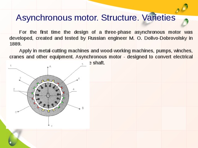
Asynchronous motor. Structure. Varieties
For the first time the design of a three-phase asynchronous motor was developed, created and tested by Russian engineer M. O. Dolivo-Dobrovolsky in 1889.
Apply in metal-cutting machines and wood-working machines, pumps, winches, cranes and other equipment. Asynchronous motor - designed to convert electrical energy into mechanical energy on the shaft.
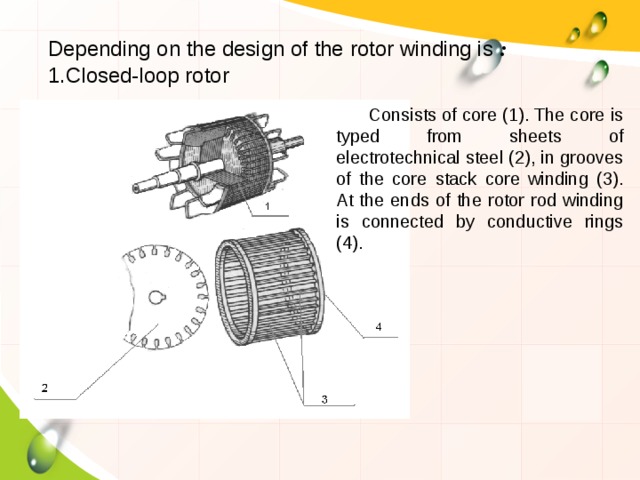
Depending on the design of the rotor winding is :
- Closed-loop rotor
Consists of core (1). The core is typed from sheets of electrotechnical steel (2), in grooves of the core stack core winding (3). At the ends of the rotor rod winding is connected by conductive rings (4).
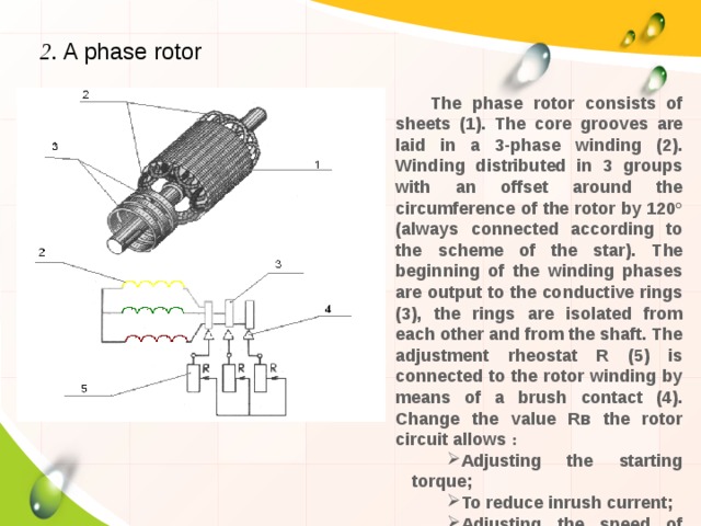
2. A phase rotor
The phase rotor consists of sheets (1). The core grooves are laid in a 3-phase winding (2). Winding distributed in 3 groups with an offset around the circumference of the rotor by 120° (always connected according to the scheme of the star). The beginning of the winding phases are output to the conductive rings (3), the rings are isolated from each other and from the shaft. The adjustment rheostat R (5) is connected to the rotor winding by means of a brush contact (4). Change the value Rв the rotor circuit allows :
- Adjusting the starting torque;
- To reduce inrush current;
- Adjusting the speed of rotation of the shaft.
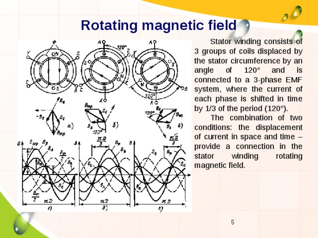
Rotating magnetic field
Stator winding consists of 3 groups of coils displaced by the stator circumference by an angle of 120° and is connected to a 3-phase EMF system, where the current of each phase is shifted in time by 1/3 of the period (120°).
The combination of two conditions: the displacement of current in space and time – provide a connection in the stator winding rotating magnetic field.
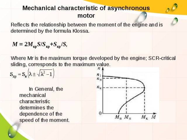
Mechanical characteristic of asynchronous motor
Reflects the relationship between the moment of the engine and is determined by the formula Klossa.
M = 2 M кр S / S кр + S кр / S ,
Where Μr is the maximum torque developed by the engine; SCR-critical sliding, corresponds to the maximum value .
In General, the mechanical characteristic determines the dependence of the speed of the moment.
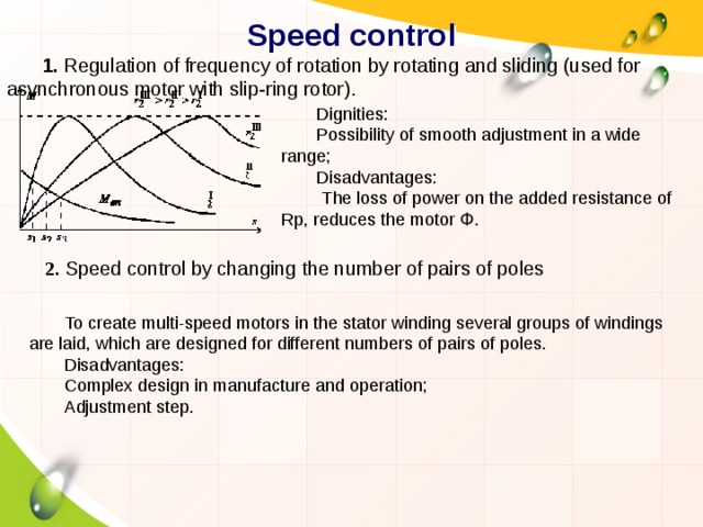
Speed control
1. Regulation of frequency of rotation by rotating and sliding (used for asynchronous motor with slip-ring rotor).
Dignities:
Possibility of smooth adjustment in a wide range;
Disadvantages:
The loss of power on the added resistance of Rp, reduces the motor Փ.
2. Speed control by changing the number of pairs of poles
To create multi-speed motors in the stator winding several groups of windings are laid, which are designed for different numbers of pairs of poles.
Disadvantages:
Complex design in manufacture and operation;
Adjustment step.
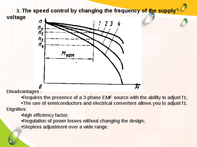
3. The speed control by changing the frequency of the supply voltage
Disadvantages :
- Requires the presence of a 3-phase EMF source with the ability to adjust f1 ;
- The use of semiconductors and electrical converters allows you to adjust f1 .
Dignities:
- high efficiency factor ;
- Regulation of power losses without changing the design ;
- Stepless adjustment over a wide range .
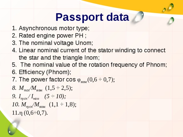
Passport data
- Asynchronous motor type;
- Rated engine power PH ;
- The nominal voltage Unom;
- Linear nominal current of the stator winding to connect the star and the triangle Inom;
- The nominal value of the rotation frequency of Phnom;
- Efficiency (Phnom);
- The power factor cos φ ном (0,6 ÷ 0,7);
- М max /М ном (1,5 ÷ 2,5);
- I пуск / I ном (5 ÷ 10);
- М пуск /М ном (1,1 ÷ 1,8);
- η (0,6÷0,7).


Вебинар для учителей

Свидетельство об участии БЕСПЛАТНО!